Making the HAC-2 joystick

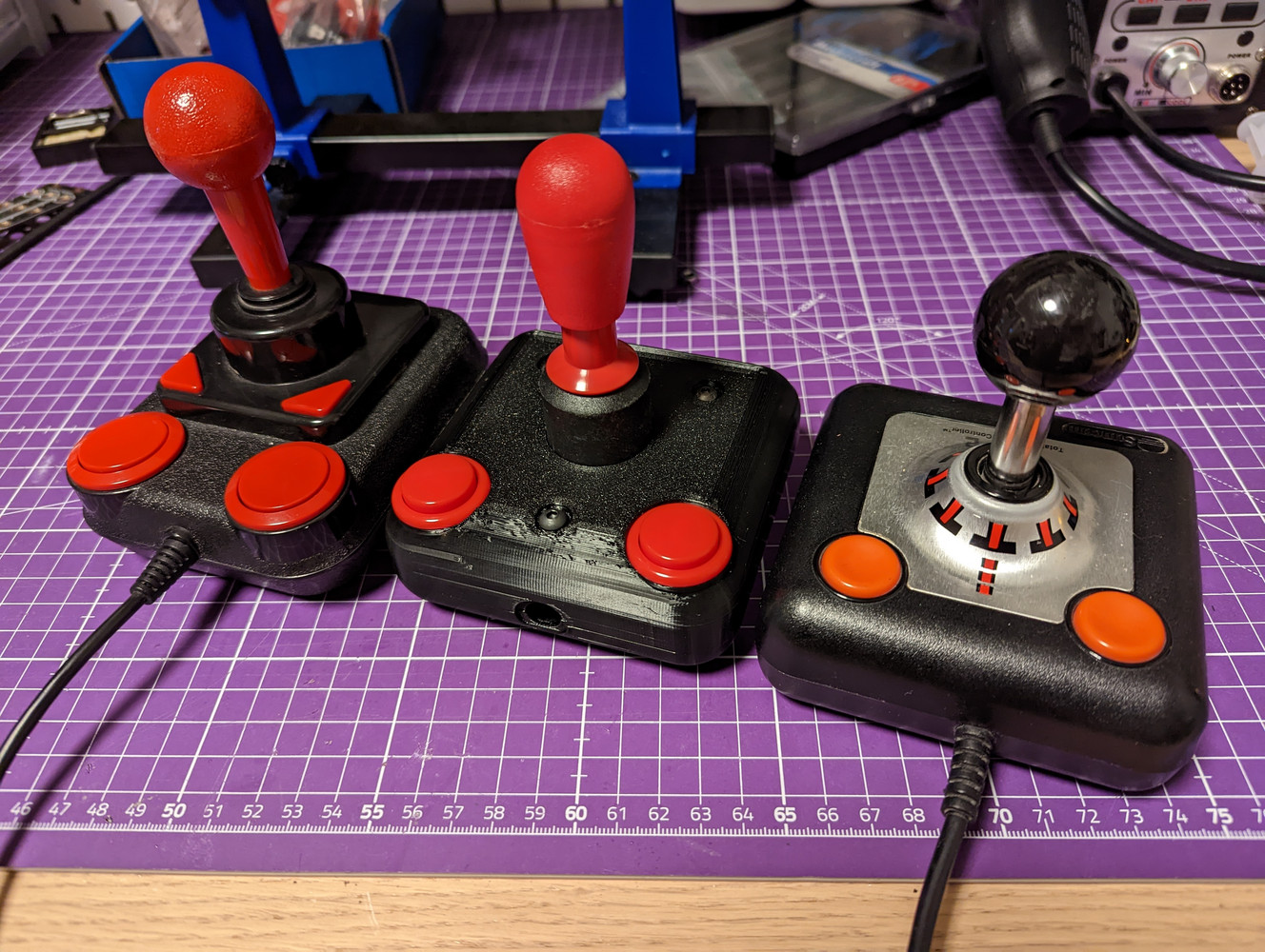
When it comes to favourite joysticks on retro computers, people tend to split into two camps: Suncom TAC-2 and Kempston Competition Pro. If you’ve read my earlier articles, you might’ve noticed that I actually kind of like them both, since each joystick has its strong points. So - what kind of joystick would you get if you were to combine those together?
Both are ambidexterous and feature simple and durable designs, but if I were to list the strong points for each of them, these might be the most important ones:
TAC-2
- Square aspect footprint with the stick in the center
- Compact case, comfortable to use handheld in different orientations
- Short stick, engages the switch contacts with very small movements
- Non-clicky buttons are are fast to press rapidly
Competition Pro
- Microswitches provide tactile feedback when they close
- Standard size switches allow for easy modding and repairs
- A “pedestal” below the stick with the pivot point inside allows two-finger use
- Large arcade-style buttons
- Comfortable handle with plastic over a metal shaft
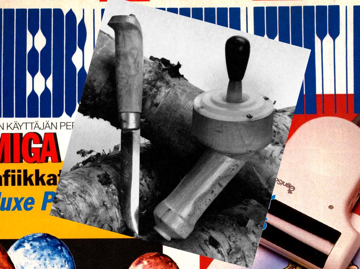
Some decades go, the finnish computer magazine Mikrobitti published an article where the author built a custom joystick into a wooden case. I remember being really impressed by it, and the idea of building a joystick myself has been lingering somewhere in my mind ever since.
Then one day in 2022, some synapse in my brain woke up from its slumber and suddenly that idea popped back into my mind. After more than three decades, the feasibility of the idea has increased substantially - thanks to easy access to 3D printing, and cheap prototype PCB fabrication. The barrier of entry has lowered even further by multitudes of online stores that offer a wide variety of components, all with detailed data sheets.
The software available these days is also miles ahead of those years, and there are several high quality CAD and EDA software tools to choose frome - many of them even free to use.
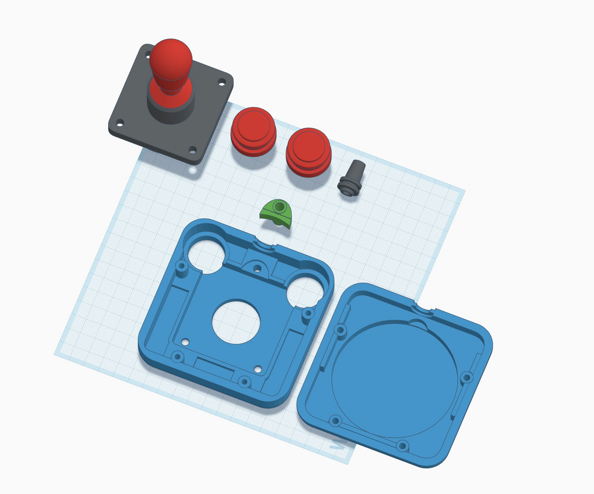
While I do know that Tinkercad is not really a professional CAD tool, I still tend to gravitate towards using it due to its ease of use for quick 3D idea sketching. And as we know, quick test projects sometimes have a tendency to blow up in scope.
Designing a case and selecting components⌗
To start off with the design, I chose to take the dimensions of the TAC-2 case as-is, since to my hand the size and shape is close to perfect. A slight modification is increasing the radius of the rounded edges in comparison to the original. While this does make printing the case slightly more difficult by requiring supports on the build plate, it feels slightly more comfortable to hold.
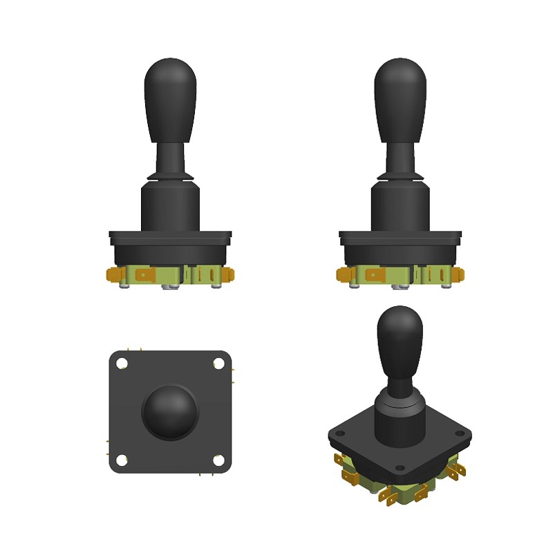
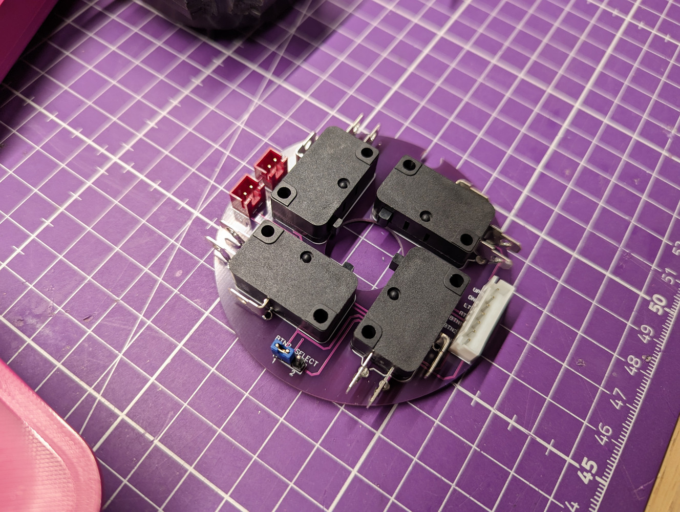
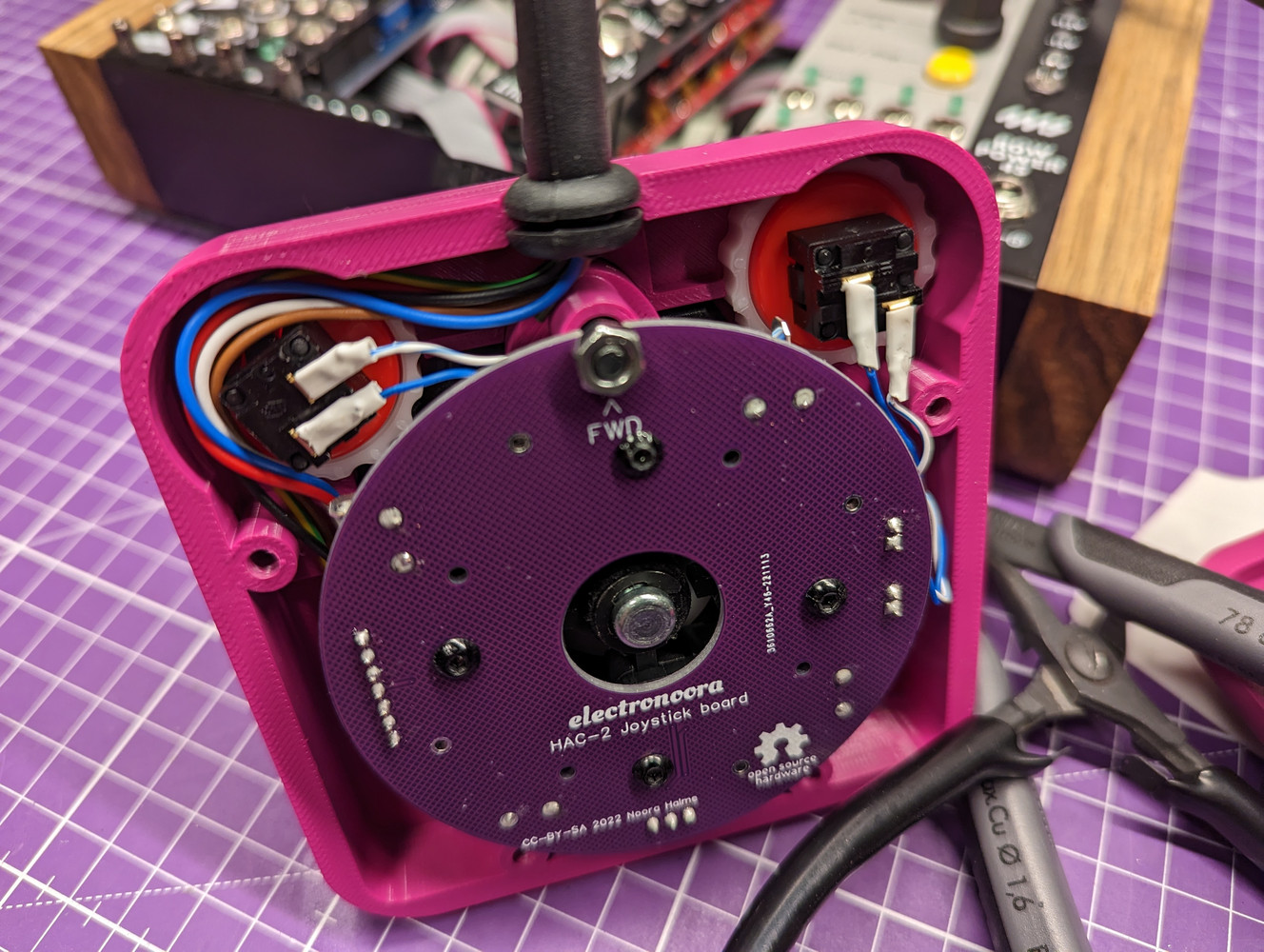
Several arcade cabinet parts manufacturers offer a multitude of joystick modules, but I quickly found that many of them have quite large mechanisms in comparison to the diminutive case of the TAC-2. Eventually I discovered the P/SM-30 joystick assembly from Industrias Lorenzo, which is compact enough to comfortably fit into the volume of a TAC-2 case. It takes four stardard V15 micro switches, so there’s a great selection of switches with varying actuation forces to choose from.
The stick itself also provides some resistance, as it is self-centered by a pre-loaded spring in the assembly. It’s held in place by a circlip, so it can be replaced should one desire to tune the resistance.
The P/SM-30 joysticks don’t seem to be particularly widely available, but I did find a few units from Partco in Finland. Industrias Lorenzo being a Spanish company, some arcade parts shops in Spain also seem to carry the P/SM-30.
Another headscratcher caused by the small case came from the buttons, as the TAC-2 buttons are rather small in comparison to the arcade stardard 30mm buttons. Even with the reasonably compact joystick assembly, the buttons would intersect it pretty significantly. Fortunately both Seimitsu and Sanwa also offer 24mm versions of their buttons, and while they still won’t fit as-is, they only overlap two corners of the joystick mounting plate. I figured that I can design an alternative mounting for the front of the joystick assembly and just cut off the intersecting parts of the mounting plate. To measure how much to material to remove, I printed out a small template.
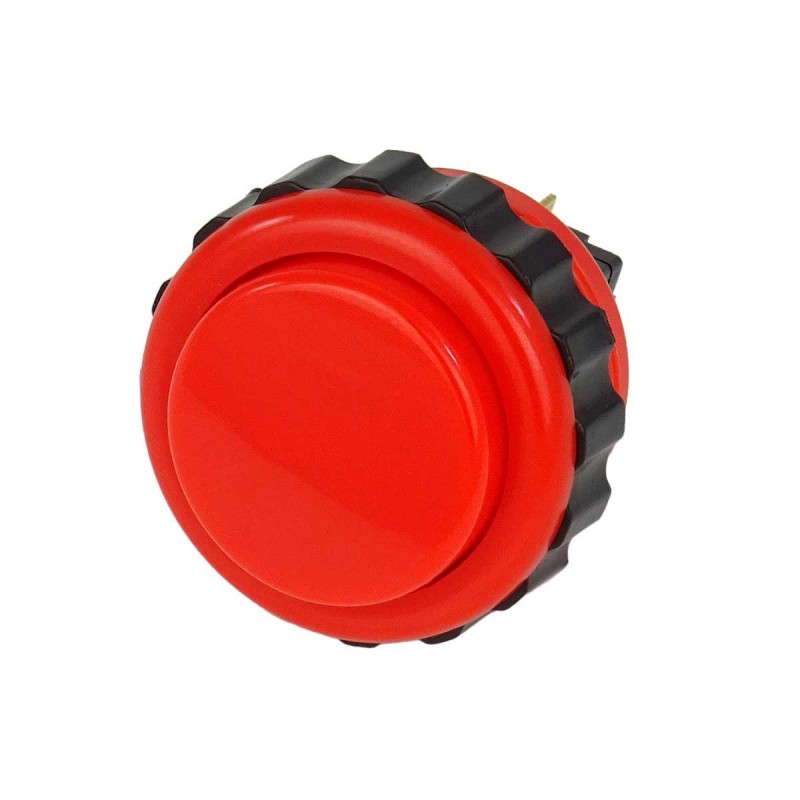
The buttons I chose for the joystick are 24mm Seimitsu PS-14-DN buttons, which have a flat top and have a more TAC-2 -like click-free action. Despite them being the smaller size button, fitting them near the radiused edge of the case required adding slight flares on the front corners to lift the buttons to the same level as the top of the case. Incidentally, this is also how the original Competition Pro was able to fit such large buttons to the joystick.
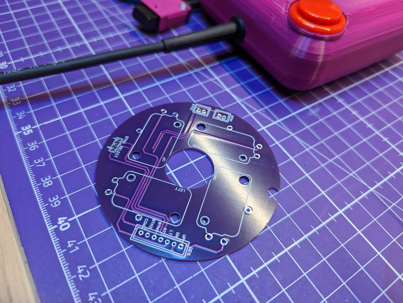
Both of my favourite vintage joysticks have taken a cost-reduced approach for the internal wiring, by simply just soldering the conductors on the DE-9 cable directly to the switch contacts. As my intent is to just build a handful of joysticks, I opted to design an actual circuit board in EasyEDA instead. This makes the joystick easier to disassemble and modify, as the buttons and cable can be attached using connectors. Since some Amiga games also support joysticks with two individual buttons, I added a jumper for selecting whether both buttons are mapped to button 1 (pin 6), or to two separate buttons (pins 6 and 9).
3D printing and iterating the prototype⌗
With both the 3D models and PCB ready to go, it was time to print out the first prototype. Given that the joystick is likely to experience a fair amount of torque and stress, I did not consider using PLA, but chose PETG filament for its superior flexibility. I did also consider ABS, but my Voron was down for upgrades and I had to print with an open frame CR-6 SE.
My print settings for all parts is 4 perimeters, 5 bottom layers and 5 top layers. Infill density is 10% using the rectilinear infill pattern in SuperSlicer. As already mentioned above, the models need auto-generated supports on build plate.
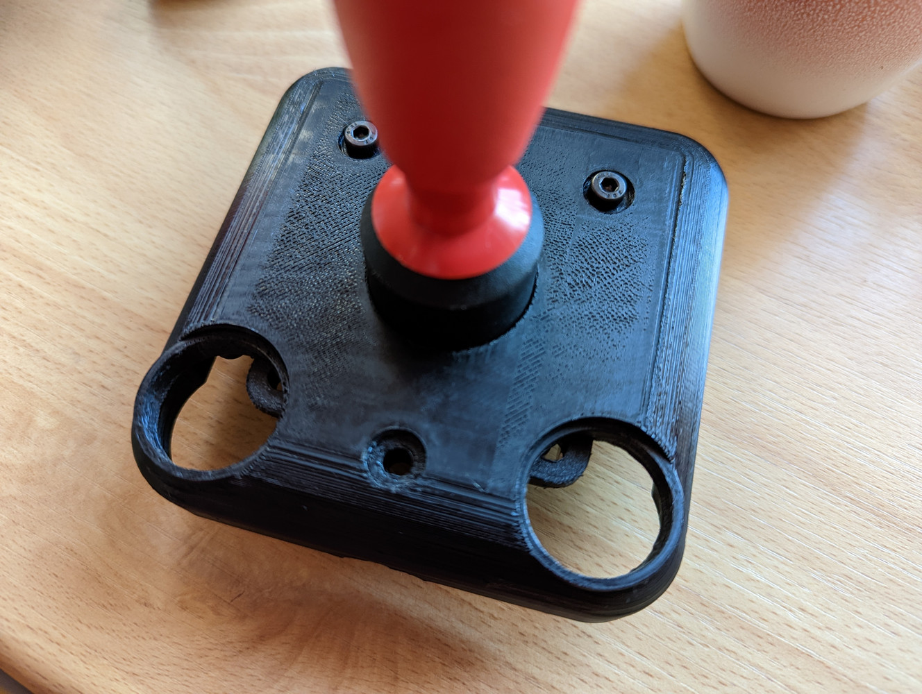
The first prototype print was using black PolyMaker PETG, with the seam facing the build plate and ironing turned on for the top surface. The good news was that it looks very, very nice. The bad news is that the case doesn’t fully close due to multiple issues.
The first prototype called for the following issues to be fixed:
- Printing with the seam side against the print plate on an open-frame 3d printer might cause seam gaps due to warping. Also needs significantly more support - ie. wasted filament.
- Added a fourth screw to hold the case halves together a bit better and mitigate warped seams.
- Heads of the screws holding the microswitches hit the bottom case floor. Modified the bottom half to make the floor thinner.
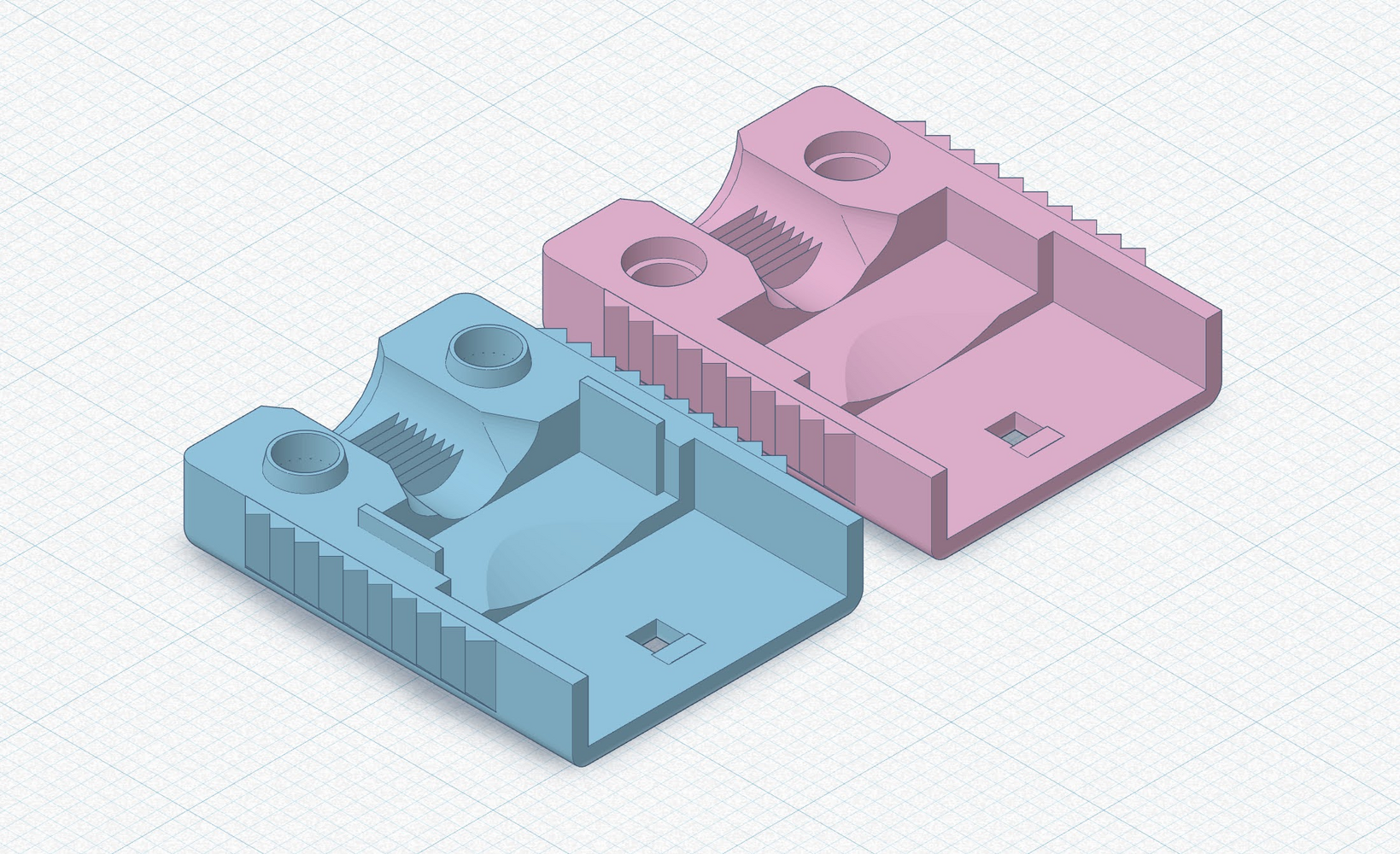
- The front mounting screw through the internal brace also hits the the bottom case, so I added a small cutout to make additional space for it.
- Not enough space around the front center to properly fit a grommet. Redesigned the internal support brace to provide more clearance.
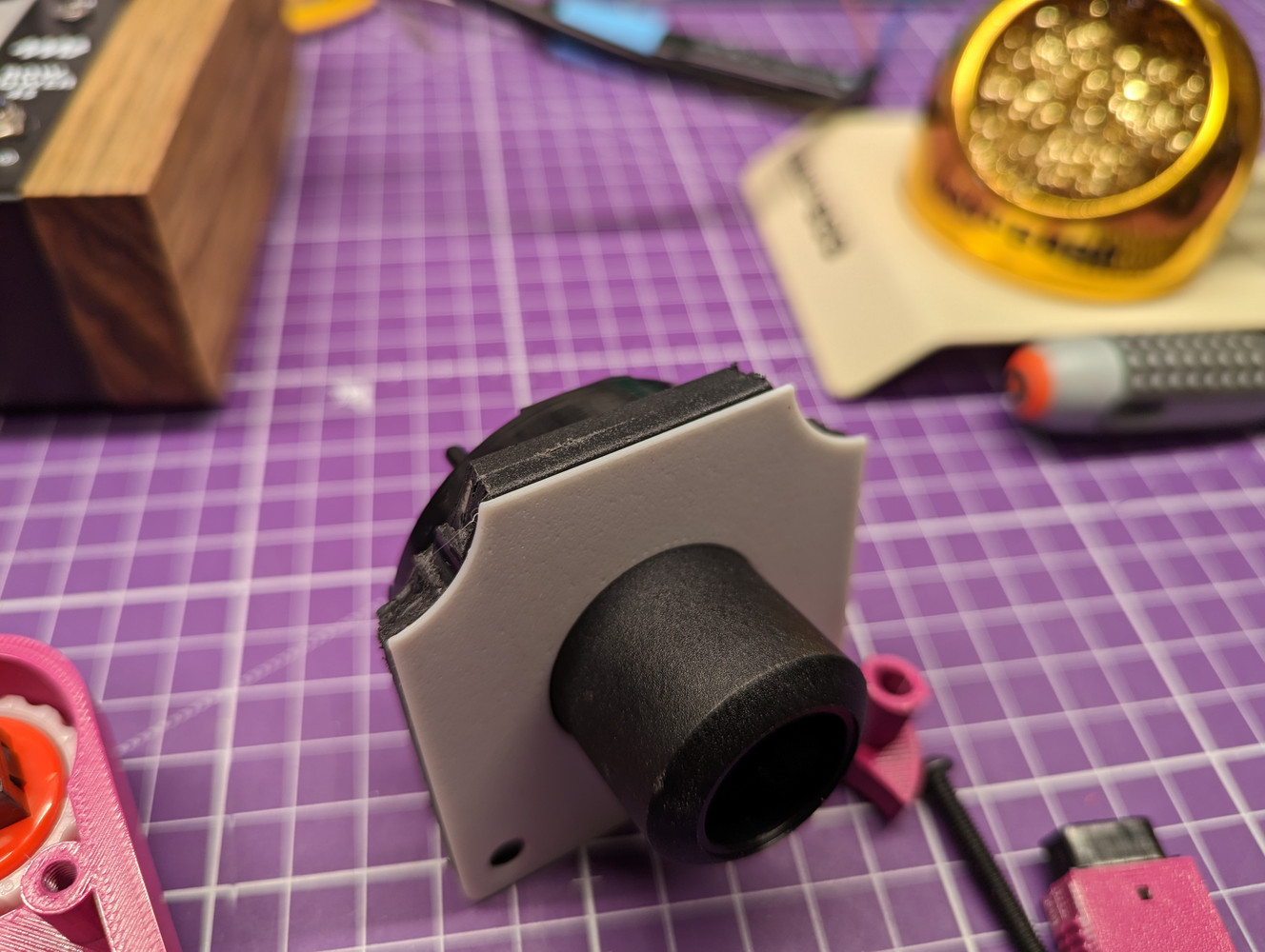
With all the fixes implemented to the design, time to print another prototype. This time the case closes completely - yay!
A few minor issues still remained, though:
- Printing with seam side up still needs supports around the edges. May need some post-processing with a file or sandpaper after supports have been removed.
- Screw heads on the bottom case extend slightly outside the curvature of the case and rub against the palm when handheld. I moved all four screws 1mm inward.
- Added small ridges to the inside edge of the bottom case to help with alignment to the top case.
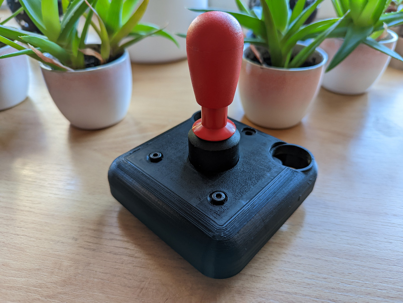
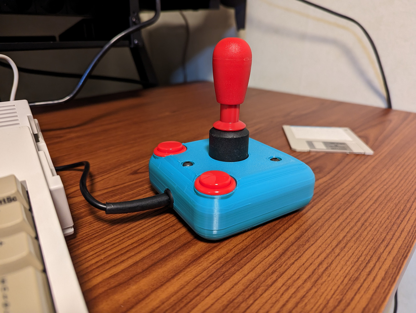
As the next print is likely going to qualify as the first “production” unit, I switched from the black PETG filament to a fancier color Extrudr PETG. And as I had hoped, no further issues came up. Now all we need is a cable to plug it into an Amiga and give it a try!
Connector and cable⌗
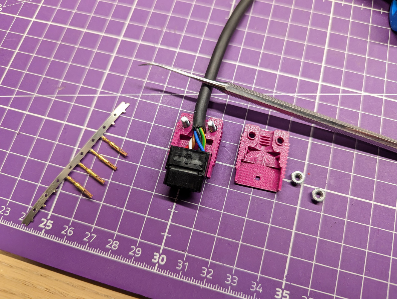
To minimize the risk of destroying chips when inevitably plugging/unplugging mice/joysticks while the Amiga is powered on, DE-9 connectors with an all-plastic shell are very much recommended. One approach is to buy factory-made extension cables and cut the other connector off, but I wanted a fancier connector that can be color matched with the joystick itself.
All-plastic connectors are not that easily available, but TE Connectivity still produces AMP 207752-3 9-pin D-sub connector with an all-plastic body. It takes nine AMP 205090-1 crimp contacts and the shell snaps closed, holding the contacts in. The housing/strain relief 207753-1 is no longer manufactured, so it’s kind of necessary to design my own housing for it.
Since the connector shells have some smaller details, I printed them with 0.12mm layer height on a 0.4mm nozzle. Since I printed the halves with the visible side against the build plate, I had to turn on supports again because of the recessed screw holes.
Playtesting⌗
Now finally with a cable, the joystick was ready for playtesting. I decided to perform this by playing a bit of International Karate Plus on an Amiga A1200. Overall the joystick performed admirably, but the stock centering spring in the P/SM-30 module might be slightly too strong when playing handheld. A suitable replacement that could be ordered in small quantities wasn’t easily found, so I will leave the fine-tuning of the centering resistance as a future development.
One possible future improvement might also be redesigning the four screw holes on the top cover to take standard threaded inserts. Current design requires tapping the holes with an M4 thread, which isn’t optimal.
Since the bottom half of the case sits very close to the PCB, this will also allow the possibility to add features that can be accessed through holes on the bottom. For example, an autofire circuit could be added and a switch exposed through the bottom.
As I was happy with the joystick as it is now, with the exception of maybe tuning the spring a little bit, I fired up my 3D printer again to assemble a second one just to test that the finished design can be built without any issues. I used filament with a contrasting color to make it easy to distinguish the two joysticks.
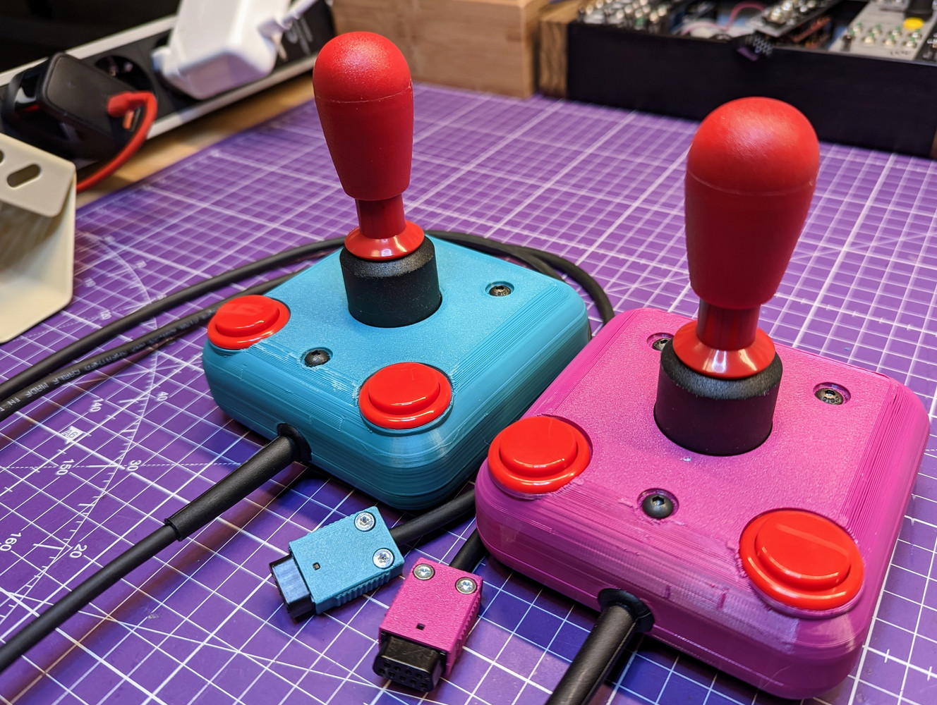
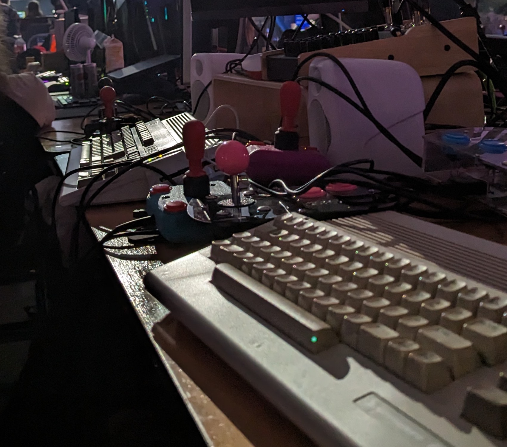
Building the second joystick was a breeze, and the two have been in use since, notably getting a trial by fire at Assembly Summer 2023 through intensive bouts of Dynablaster and TurboRaketti II.
Building your own⌗
For anyone interested in building their own HAC-2 or hacking the design further, here is a complete list of parts and files required.
Bill of materials
| qty | Description |
|---|---|
| 1x | Industrias Lorenzo P/SM-30 joystick assembly |
| 2x | Seimitsu PS-14-DN arcade buttons |
| 4x | Zippy VM-05B microswitch (or Cherry D44X, or any similar) |
| 1x | M4x35mm button head cap screw |
| 4x | M4x20mm button head cap screw |
| 2x | M4x16mm button head cap screw |
| 4x | M3x16 button head cap screw |
| 2x | M4 locking nut (nylock) |
| 1x | M4 nut |
| 1x | Essentera grommet sleeve RGS1-60466 |
| 2x | JST B2B-XH-A wire-to-board connector |
| 1x | JST B7B-XH-A wire-to-board connnector |
| 2x | JST XHP-2 connector housing |
| 1x | JST XHP-7 connector housing |
| 11x | JST SXH-002T-P0.6 crimp contact, 26AWG |
| 1x | 3-pin header |
| 1x | jumper block |
| 1x | TE Connectivity 207752-3 DE9 connector shell |
| 9x | TE Connectivity 205090-1 crimp contacts |
| 2x | M3x8 barrel head torx screw |
| 2x | M3 nut |
| 2-3m | 6- or 7-conductor unshielded cable |
Printable .stl files for the joystick:
- Top case (533KB)
- Bottom case (514KB)
- Front brace for joystick module (72KB)
- Shorter, alternate brace (45KB)
- DE-9 connector shell top (203KB)
- DE-9 connector shell bottom (167KB)
- Cutting template for the joystick module (48KB)
Fabrication files for ordering the PCB:
- Gerber files for joystick PCB (59KB)
- Schematic for the PCB (22KB)
The files above are licensed CC-BY-SA and also available on Printables.com. Let me know if you build a HAC-2 for yourself or improve the design with new features! :)